|
Special Features:
■
2-ports(RJ-45) Ethernet
10/100 Based-T Comm.
■
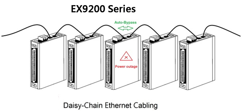
Daisy chain connection with auto-bypass
protection
■
Support
Modbus/TCP,TCP/IP,UDP,ICMP,ARP
■
Support
Automatic DIO Sync.(peer-to-peer).
■
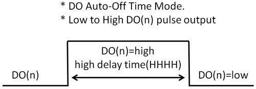
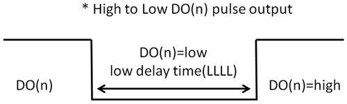
DO Auto-Off Time Mode.
■
Support 4 Relay
output,0.6A@125VAC/2A@30VDC, RL0,RL1,RL2 Form C and RL3 Form A.
■
Support 4 Isolated
differential digital input
■
Fully Photo-Isolation 3750Vrms
■
Protocol:
ASCII Format & Modbus TCP
Specifications/
| Interface: |
|
Communication |
2-port(RJ45)
Ethernet 10/100 Based-T
comm, Daisy chain connection with auto-bypass
protection. |
| Protocol |
Modbus/TCP, TCP/IP, UDP, ICMP and
ARP |
| Led
indication |
Led for power and Ethernet link
status |
| Isolation Digital Input: |
| Input channels |
4 (DI0~3) |
|
Input type: |
Differential
●
logic level 0: +10V to +30VDC max
●
logic level 1: +0V to +1VDC max
Logic level status can be inversed via ASCII/Modbus
command |
| Counter Input |
300Hz counter
input (32-bit+1-bit overflow) |
| Input Impedance |
2K ohm |
| Optical
Isolation Voltage |
3750Vrms |
| Relay Output: |
| Output channels |
4 (RL0,RL1,RL2
Form C(SPDT) and RL3 Form A(SPST NO) |
| Relay type: |
Surge
strength: 500V
Relay contact rating: 0.6A/125Vac, 2A/30Vdc
Operate Time: 3mS max.
Release Time: 2mS max.
Min Life: 5*105 ops |
| Pulse output |
Each channel
supports 300Hz pulse output |
|
Power
requirement: |
| Consumption |
2.5W (Typical) |
| Power input |
10~30VDC |
| Operating
temperature: |
-10 ~ 70° C
(14 ~ 158° F) |
| Operating
temperature: |
-25 ~ 85 °C
(13 ~ 185 °F) |
| Humidity |
5~95% RH,
non-condensing |
|
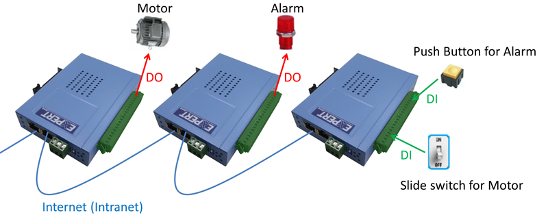
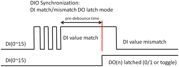
Features:
Automatic DIO Synchronization (peer-to peer)
EX9200-MTCP series module also provide a Automatic DIO
Synchronization function. With peer-to-peer networking, users
can define the mapping between a Pair of EX9200-MTCP series
modules so that input values will be directly transferred to
output channels. A single digital output channel(Local/ Remote
device) is activated(1/0 or toggle)dependent on the digital
input channels state data pattern. When the specified DI
channels state data pattern changed from “Match” to “Not match”
the corresponding DO well be set to active(1 or 0).
|
|
;)
;)
;)
;)
;)